Caring for and designing with audio jacks
Audio jacks are... a mess. There are at least 4 different sizes, of which 2 are common, that are called by different names across the Atlantic. There's a variable number of contacts and at least two different schemes for using them. Originally designed for telephone exchanges, they're now used for general consumer audio as well as professional recording equipment. Some are even used for power, for connecting guitar pedals... The "jack connector" may as well be more of an idea than an actual standard.
Nonetheless, in the consumer space, today, there are de facto standard uses for jack connectors. Here, I try to provide an overview of what to expect when tinkering.
Electrical interface
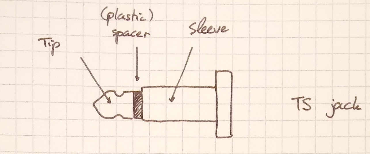
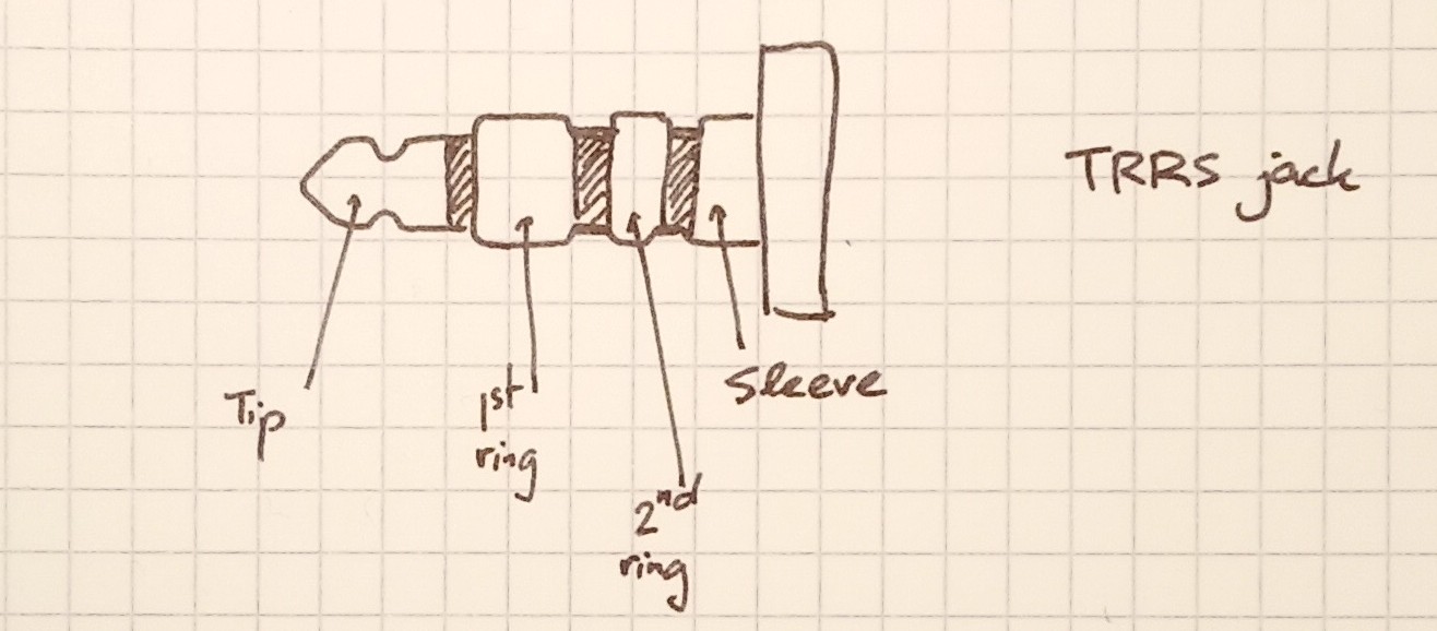
Audio jacks have between 2 and 4 contacts. The contact farthest to the cable is called the tip, and the one closest is called the sleeve. All other contacts, if any, are called rings. Jacks exists with no rings (they're called TS jacks) and up to 2 rings (TRRS jacks).
Electrically, they are wired as follow, going from the tip to the sleeve:
-
Tip: carries the left channel if stereo, or the only channel if mono.
-
Ring 1 (if present): right channel; implies stereo operation.
-
Ring 2 (if present): microphone, for combined speakers+microphone headsets. In some headphones, media buttons (play, pause...).
-
Sleeve: common voltage reference for all signals, GND.
A feature of this design is that if a cable is used that has less rings than what the plug expects, degradation is smooth. If a device expected a TRRS jack for microphone use, but a more common TRS jack was inserted, the device will read the microphone as being shorted to GND (since the sleeve will extend in the space taken by an hypothetical 3rd ring). Therefore, microphone functionality will be inoperative, but the stereo carrying function will work as usual.
Nowadays, most plugs stick to the TRS stereo design. I've only encountered TRRS jacks in phones and laptops where the combined headset operation makes sense. In the past, some funkier designs cohabited -- I heard of TRS jacks where the ring was a power supply for a microphone and the tip carried the mic's output. Today, the power for microphones is applied to the second ring in TRRS plugs, or to the TR of TRS microphones. (Yes, those pins carry power and signal, but that's a story for another time.)
That's it for the plugs; the sockets are more complicated. It is often useful to detect whether a cable is inserted, to switch audio output for instance. To achieve this, jack sockets carry switches, that make or break contacts when a plug is inserted. The number of switches and their operation is... variable. Expect that any weird combination may potentially exist. I've found two configurations to be most common:
- either no switches at all
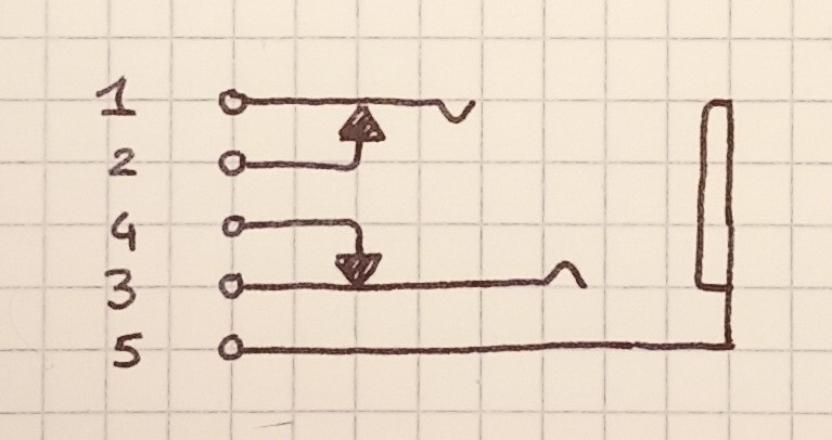
- normally closed contacts on the tip (and ring, if any) contacts. For instance,
a TRS plug might have 5 pins: tip (1), tip switch (2), ring (3), ring switch (4) and
sleeve (5). When no jack is plugged in, 1-2 are shorted, as are 3-4. But once a
jack is inserted, this is no longer the case.
This second configuration is helpful, because it allows a very nice switch over scheme. Assume a device has internal speakers and a headphone port. Then it can feed its audio to pins 1 and 3, while connecting its internal speakers to pins 2 and 4. With no plug inserted, the audio is routed to the speaker, but when the operator plugs something in, the speaker is disconnected.
This scheme used to be prevalent in the 80s and the 90s. Equipment designed afterwards usually sense the switches to detect whether something is inserted, before changing the active output in software.
Mechanics
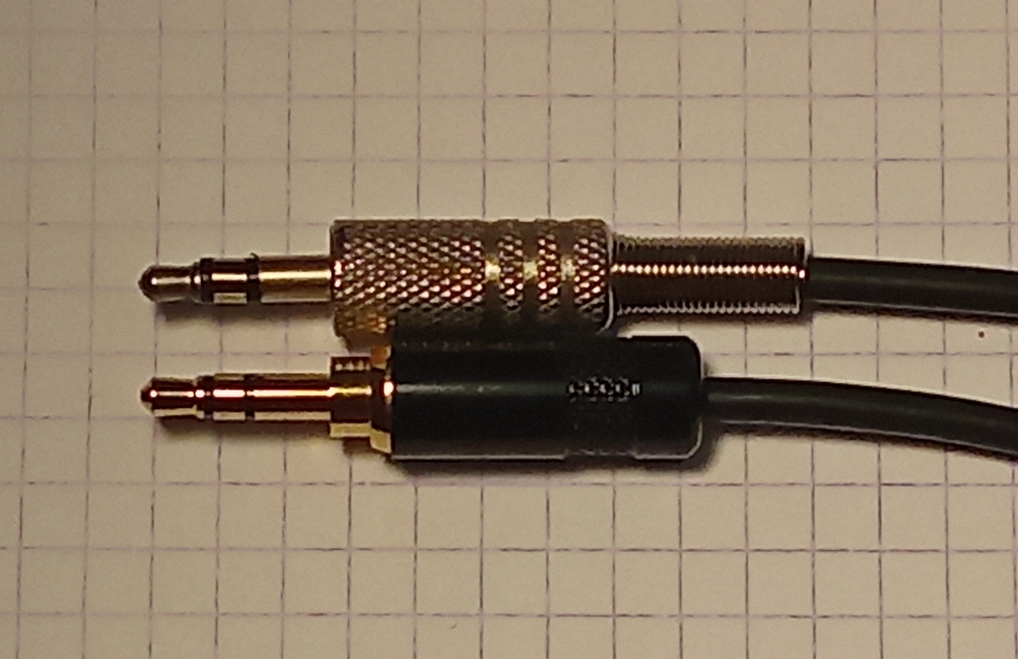
Audio jacks exist in (at least) 4 diameters: 2.5mm, 3.5mm (called 1/8" in the US, aka minijacks), 6.35mm (1/4") and the oddball 4.4mm. You will note that 1/8" jacks are not actually 1/8" wide. The 4.4mm ecosystem is specialty stuff that completely ignores the conventions laid here and even uses 5 contacts sometimes. I haven't found many 2.5mm systems out there; the connectors feel flimsy and the space gain isn't that significant. Now that phones are opting out of jacks altogether (hugh) I think we won't see many new products using 2.5mm jacks. The traditional 6.35mm jacks are standard in audio production equipment. They are usually TS, and stereo is provided using two cables.
Inside, they are all made of concentric hollow cylinders crimped to a common base. In cheaper connectors, the cylinders are made out of sheet metal welded back on itself, creating a noticeable bump. The exact profile isn't specified. While many manufacturers' products are interchangeable, there is a notable split: in some jacks, the first plastic spacer has the diameter of the tip's end, while in others it has the nominal diameter of the connector.
This might not seem like much, until you realize that the leaf contacts inside the plug have to ride the bump between the first and second contact on insertion. With the small spacer, the bump occurs at the front of the second contact; it is always filed down somewhat (otherwise it'd be sharp) and it's made of thin bronze. This makes the bump much easier to overcome than with the large spacer. Having the large spacers probably makes sense from a cost point of view, because it allows all spacers to be the same size. Having seen some plugs get damaged by that jack design, and others outright refuse insertion I'd argue for avoiding it. Manufacturers usually don't point that detail out, but a datasheet with a proper drawing will allow you to tell which is it.
Plugs exist in a variety of mounting style: they can be panel mounted then linked to the rest of the circuit through wires, mounted on a circuit board vertically or horizontally (and then optionally bolted to a chassis), or even as part of a captive cable. There's a lot to say about the different styles and their mechanical compromises. But the TL;DR is that
-
When designing, you should aim for panel mounted plugs first, then vertical PCB mounts that are bolted to the panel, then horizontal PCB mounts. Unbolted vertical mounts are a last resort and captive cables are an abomination. In any case, think about the sharing of stress and bending on the whole assembly -- this will avoid cracking solder joints. Also, try not to use fancy switch configurations, or if you do, make your device tolerant to plugs that might not implement all switches.
-
When replacing plugs, keep in mind whether the plug's chassis directly connects to the instrument's chassis. If these are conductive, which is usually the case, this plays into signal integrity issues. The how and the why is fascinating and complicated, I may write about it later. The instrument was designed one way, it's better to keep it that way unless you know what you're doing. You may need plastic nuts.
When stuff breaks down -- cable, jack or plug?
Audio cables break. Some of that may be a consequence of being among the most mistreated of their kind. Think about it, does any other cable you own suffer dynamic loads and shocks on a daily basis? Anyway, for repair purposes it's useful to identify exactly what broke. Here are the usual signs I look out for when debugging a faulty connection between a device and a headset (say).
-
If the device keeps complaining about disconnects, something is probably wrong in the plug. Indeed, most plug in detection switches don't care about the headset being present, or the jack being connected to a cable: all that matters is the jack's shape. Most detection switches use the sleeve contact. That's unfortunate, because the jack is held by the dent in the tip. Meaning that the sleeve contact is the one that'll have most play.
-
Another consequence of the way the jack is held is that the right channel is more susceptible to intermittent contact than the left channel. That's not in itself a diagnostic, but it's something to keep in mind.
It is possible to diagnose jack/plug interface issues by applying radial force on the jack while it's inserted. If some direction makes the problem consistently go away, or change, then the cable itself is probably fine. I have seen one case of jack failure, in which the crimping in the ring contact was bad. It was possible to rotate it relative to the rest of the assembly! If the jack is bad you can salvage the cable by cutting right above the connector. If the plug is bad... Well, I hope you can source an exact replacement, or hack your system to accept a new kind.
- If the previous symptoms are not present, then the problem is usually in the cable. Consider which end of the cable is subject to most strain in daily use, and that in a headset one of the channels has to go from the left to the right side of the set, which adds extra points of failure. To test a point of failure, gently jiggle the suspected break while keeping the other end of the cable relieved. If the failure is still intermittent you'll hear a crackle in the defective speaker.
Since captive cables usually break near their free end, it's usually possible to trim the cable a bit then assemble a new connector. If the cable breaks near the base it's usually game over, sourcing a replacement is a pain and a hack has to be devised. If having to design around a captive cable, I find it nice to ship the device with a cable on the long side, so it can be repaired a few times. For headsets, 90cm is a good starting point.
I feel it is necessary to send a note to mixing engineers out there. When mixing stereo, not having the instruments in the center is arguably the point. And it is usual in a piece to bring the band in player by player. But please try to avoid having your mix purely on one channel in the intro. It's too easy to have the bass track start first, and mix it to the right. But then a headphone user will suspect their left speaker has gone bad until the centered percussions come in! This is an unneeded inconvenience, since in real life no instrument is hard-left or hard-right in a venue. You can mix the bass on the left channel 20dB down and it'll be fine: once the other instruments come in it'll be unnoticeable. This has a similar purpose to telecom comfort noise.
It's a beautiful, beautiful mess
I hope the insights given above will help you debug some faulty devices, or help you design your own. A running theme, as you've noticed, is that nothing is really standardized here and it is very much a free-for-all. That'd be a textbook bad thing in most cases, but I'll argue that in the hacker scene it's not so bad. A jack cable is a convenient and cheap way to bring a few wires from point A to point B. Make it the connection to your machine's foot switch! You wouldn't be the first. But be considerate. Document when you are straying far from the beaten path and expect that users are going to plug their stereo into your foot switch. Make an honest effort to stick to the standards, even though they're not perfect for your application. Different kinds of equipment have different traditions; if you're building audio production equipment, use 6.35mm TS jacks. Once your build is done these details give it personality; do you want to build something humble or demanding?